A crash course on mechanical stability
Mechanical stability is a concept borrowed from mechanical engineering. Its application to biomechanics was first introduced in the late 1980s by Swedish mechanical engineer and biomechanist Anders Bergmark (from Lund), who proposed mechanical models of the ankle joint and spinal joints.
This post is a guest post by The Older Avocado.
Bergmark’s model could not be applied directly to the in vivo spine, because it was too simplified, but it came with a blueprint for what needed to be added to apply it to the in vivo spine. This blueprint was implemented in the mid-1990s by McGill and Cholowecky, in what would become later known as “McGill’s Model” of the spine. The model is rather complex, but as far as applications to training go, the only two things you need to understand are the following two diagrams.

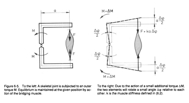
Fig. 6.5 (p. 27) from Anders Bergmark (1989) Stability of the lumbar spine, Acta Orthopaedica Scandinavica, 60: sup. 230.

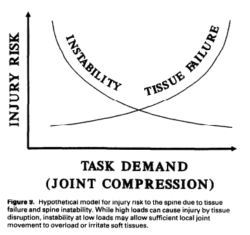
Fig 9 (p.9) from Cholewicki, J., & McGill, S. M. (1996). Mechanical stability of the in vivo lumbar spine: implications for injury and chronic low back pain. Clinical Biomechanics, 11(1), 1-15.
So let’s begin with Anders Bergmark’s biomechanical model of joint stability. On the left-hand side of Fig 6.5 from (Bergmark, 1989:27) the joint is maintained in proper alignment when subjected to torque (moment, moment of force) M. The force F originating from the muscle is sufficient to maintain this alignment. The system is mechanically stable if and only if, for some small additional torque ΔM adding up to M, the muscle could maintain the joint in proper alignment, that is, pull it back to alignment without voluntary contraction (as it does with moment M). Bergmark’s main hypothesis is that the force F here is the muscle’s mechanical stiffness.
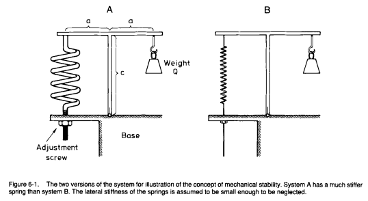
Mechanical stiffness is a property of materials best explained with the examples of springs, that serves as a simplified mechanical model for muscles in Bergmark’s model. This means that, in Bergmark’s model, muscles can be treated as springs. Here’s how: first, consider a T-structure with a weight and a spring attached to it that stands vertically on a base when the force of the spring matches the pull of the weight (see below, reproduced from Bergmark 1989:25)

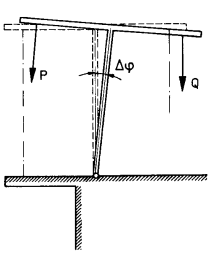
In both A and B, the T is standing because the potential energy of the spring (P) and of the weight (Q) cancel one another. But the spring in structure A is stiffer than the spring in B: it has a higher (potential) energy P than the spring in the structure B and thus could compensate for forces that would act in the same direction as Q. Assume now that we introduce a small disturbance in the system that adds up to Q (“a clockwise angular deviation Δφ”, depicted below), such that the potential energy of spring A could compensate for it, but not the potential energy of spring B. Explicitly, if the disturbance happened, the potential energy of both springs A and B would be converted in actual kinetic energy, but only spring A would pull the T back in place: with spring B, the T would still be slanted (clockwise).

The force Q tries to increase the disturbance angle Δφ, whereas the force P in the spring tries to move the system back to the equilibrium position Δφ = 0. Thus the question about stability and instability is reduced to the question about which one, P or Q, that wins.
Anders Bergmark, The Stability of the Lumbar Spine, p.25
So far, Bergmark’s analogy illustrates that both A and B are in equilibrium but only A is in stable equilibrium while B is in unstable equilibrium. More accurately, A is mechanically stable on its own thanks to the stiffness of the spring. B could be made stable through external control (a tightening of the screw by an external operator).
We can now substitute the spring with a muscle and identifying muscle stiffness with “passive stretching and spinal reflex tension modification” (Bergmark 1989:26). Passive stretching increases the potential energy stored in the muscle and is purely mechanical. The “spinal reflex” is the Liddell-Sherrington Reflex, or stretch reflex, and does not require CNS control. As such, it is not considered to be “active” (the equivalent of CNS control is tightening the screw by hand).
Bergmark does not specify further the physiological correlates of mechanical stiffness but we can equate stiffness with muscle tone, that is, the residual contraction of muscles at rest (when no voluntary contraction occurs). An important assumption of Bergmark’s model is that our joints are not in stable equilibrium even absent pathologies that may affect joint alignment (such as muscle imbalances caused by too much sitting, or the lingering consequences of past injuries). Unstable equilibrium lowers metabolic maintenance costs (muscle contraction costs energy) and is relatively safe as long as the CNS can increase muscle tension reactively when needed.
CNS reaction times are not always sufficient to protect joints against destabilizing events. Accordingly, the CNS may increase mechanical stiffness preventively (under the spring analogy, tighten the screw) when some possibly destabilizing events are anticipated. This phenomenon can be harnessed for training purposes, for instance with exercises variations that introduce unpredictable micro-movements, like bench-pressing with a bamboo bar or using kettlebells with a bottom-up grip.
The Load-Injury Curve Hypothesis (LICH). The Load-Injury Curve Hypothesis, represented by the second of the two figures at the beginning of this post, is a hypothesis proposed by Cholewicki and McGill (1996) in their application of Bergmark’s theoretical model to the in vivo spine. Although Cholewicki and McGill specify this hypothesis for spinal joints only Bergmark’s model extends to other joints, and since the curve is a consequence of Bergmark’s model, so would be its generalization to other joints as well.
End-range of motion often where instability is the highest (in particular when it involves longer moment arms) and thus where the risk of joint failure is at its highest. Therefore, getting closer to the end-range of motion increases the risk of injury through joint failure. Cholewicki and McGill give the example of how flexing lumbar spine to picking a pencil cause enough instability for the spine to buckle (Cholewicki & McGill 1996:9). Similarly, reaching out to the back seat of the car can cause enough instability in the glenohumeral joint to cause a shoulder injury. Ironically, a shoulder mobility drill with a broomstick is less likely to have similar consequences if one has ‘tight’ shoulders, since the compressive forces that result from co-contraction of the muscles surrounding a joint are protective for that joint.
Hence, it seems wise to apply some load in addition to the load of the body itself when accessing end-range of motion in cases that may cause instability. This vindicates yoga asanas that manipulate gravity or isometric tension to increase the load on joints, which are better than passive stretching, or active stretching such as contract-relax (since the end-range of motion is access after during the relaxation phase, where co-contraction is inhibited). The video below gives an example of how loading can be applied to shoulder mobility drills in order to protect the glenohumeral joint through co-contraction of the surrounding muscles.
